Friday, October 31, 2025

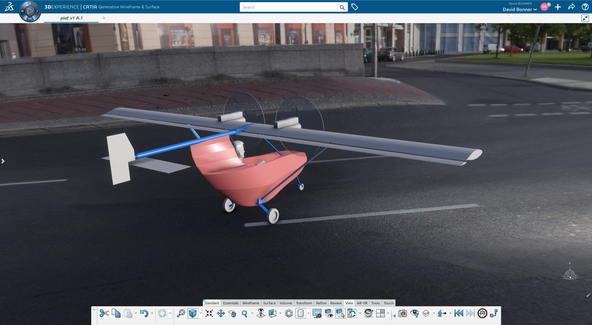
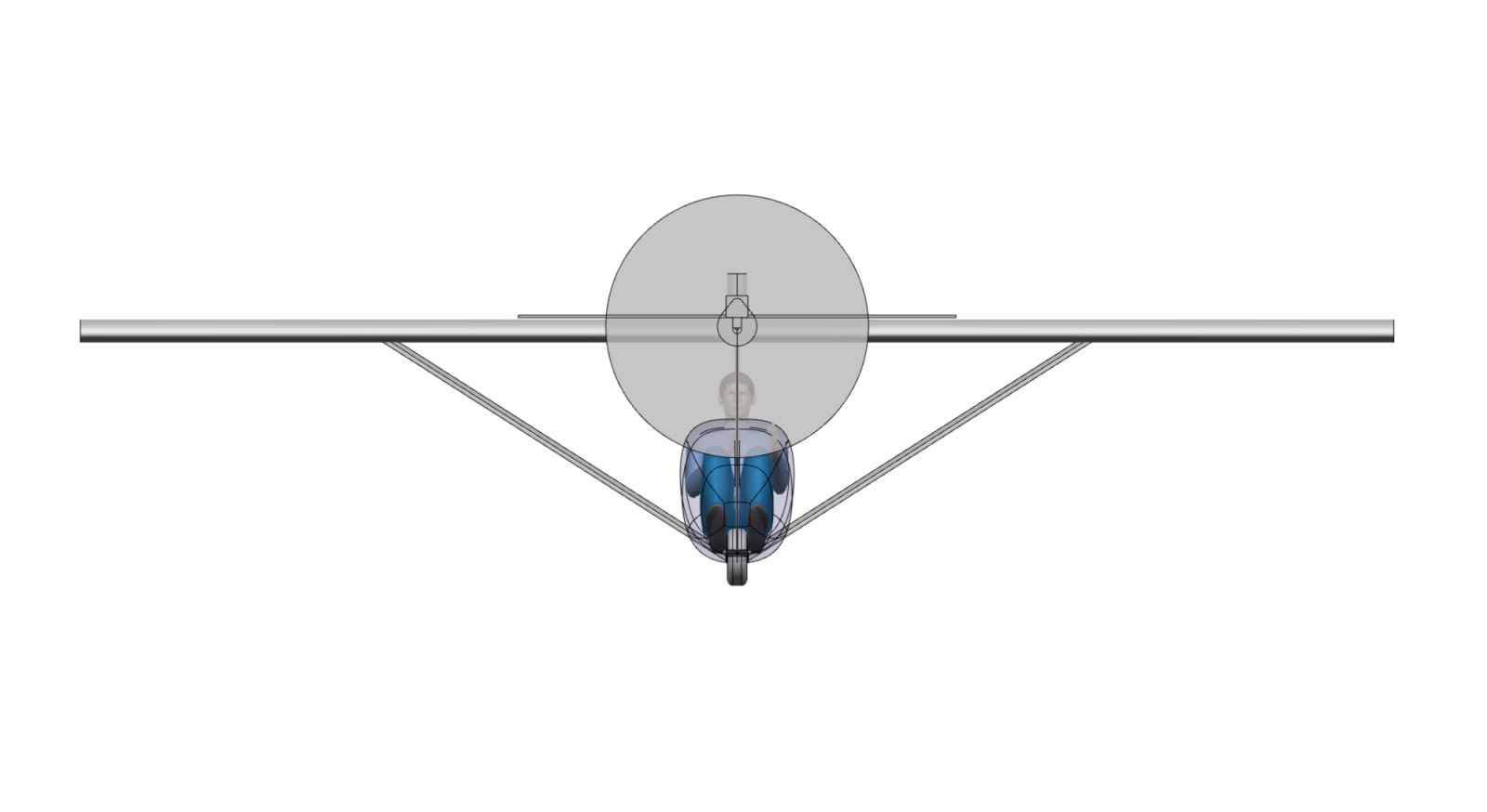
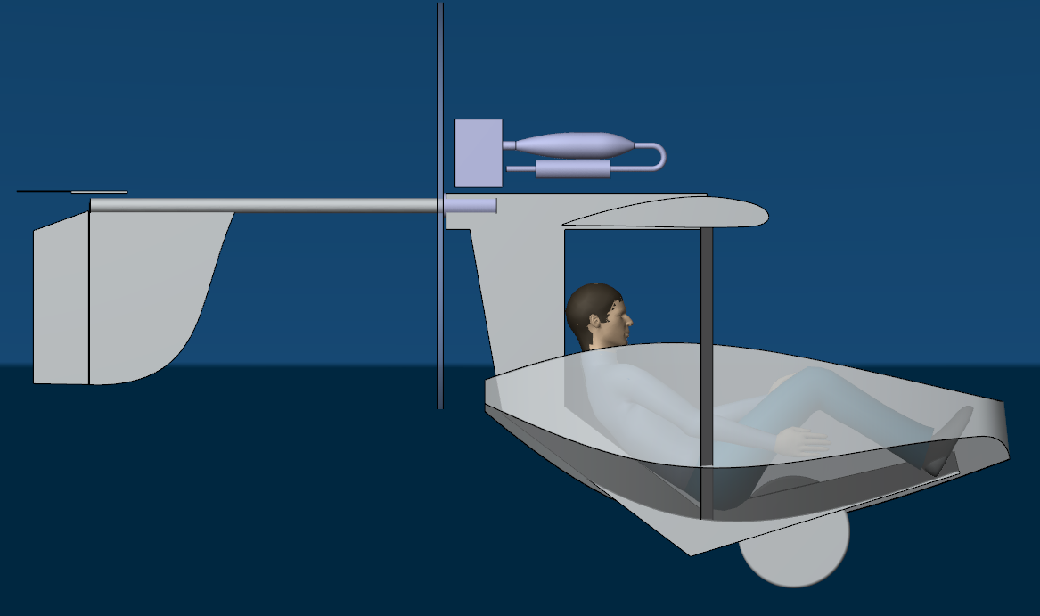
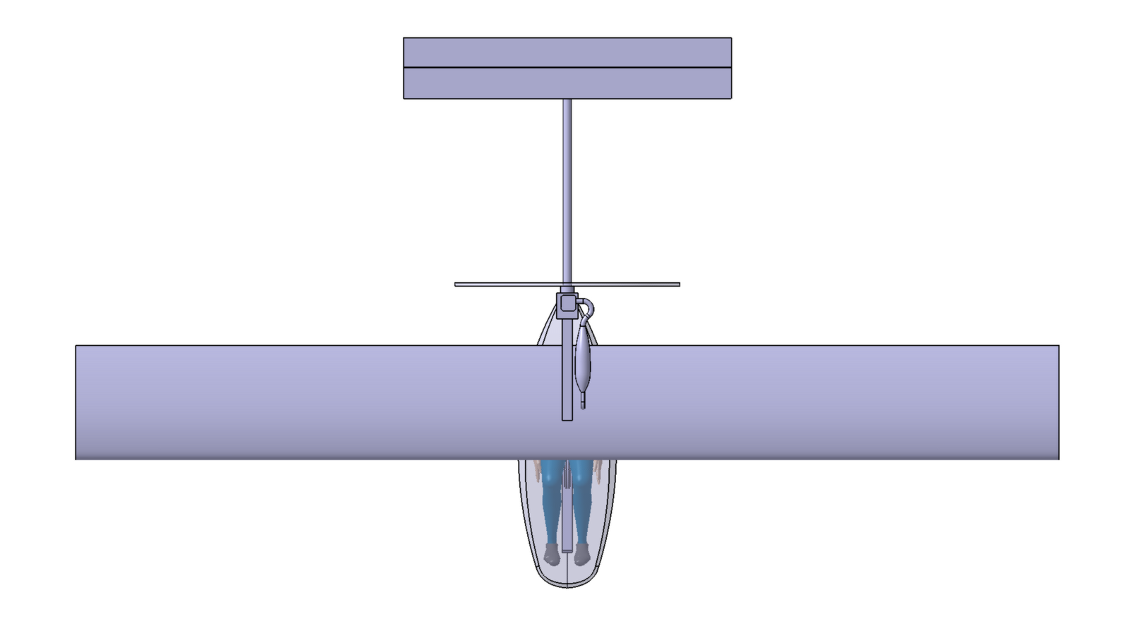
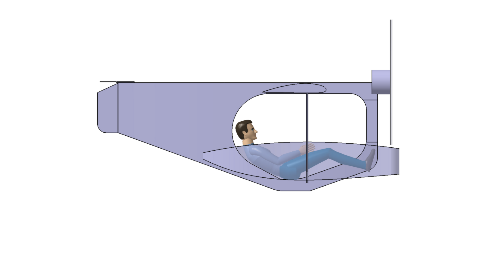
Due to the strength of the carbon fiber spar caps, it turns out there's no need for struts. An 80 mm diameter, 2mm thick carbon tube above the pilot's head transmits all of the forces from the wing. 


Note also the electric propulsion is swapped for a 3W 275 two-cylinder 2 stroke because it's much lighter & also because the best electric options were all multi-motor (we even looked into a 6 motor system, 3 pods per wing) and it's not clear whether an ultralight is legal in France with multiple motors.  

Inspiration for the wing is from two sources: Colomban Cri Cri for the high lift profile, and Hurel Dubois for the high aspect ratio on a normal aircraft (not a glider and not high altitude like the U2). 


Sunday, March 24, 2013

another version

The Center of Gravity is too far back in this picture, I need to move the wing & struts a bit further back to compensate. There is no longer any tube coming down from the engine because the carbon tube should be strong enough without any support. The pilot would be wearing an aero-helmet. 

Friday, January 11, 2013

another version with tractor engine


We said that the layout was definitive, well, no. We're still checking out alternate layouts.

Sunday, December 9, 2012

simplified structure using rigid struts

A simpler fuselage using thick, rigid struts to take the principal flight loads in positive and negative G. The fairing is the same, it's just not shown in these images

Monday, December 3, 2012

straight line fuselage

The fuselage has been modified. It's still a 60 mm wide box section but it's all made out of straight lines. The material is carbon reinforced wood and we had two reasons to migrate to a straight line shape, one is simplicity of construction (each straight segment can be a rectangle of 1mm plywood, overlapped with the next)  and also ease of reinforcement by straight carbon fiber rods included inside the structure seams. In this layout, the pilot is also lying down a bit more, to reduce frontal area and interference with the wing.

Sunday, June 24, 2012

Leading Edge D-Structure: 2.3 kg

3 meter long leading edge D structure, carries all flight loads for +6 -3 g. 2.3 kilograms including the fiberglass on the web faces. Will go up to 2.5 or 2.7 kilos when I include the metal fittings, and there will be about 100-200 g of glue. But it's still pretty light. Notice in the spar, the balsa wood, which is 120 kg/m3, is replaced by 28 kg/m3 foam on the outer 110 cm of the wing.

Thursday, June 21, 2012

Detailed Wing Structure

I'm working on the detailed wing structural model, starting with the front D-Section.
Ribs - 20 mm extruded polystyrene 28 kg/m3
Spar is 100 x 10 x 3000 mm dimension
Spar Caps - unidirectional carbon
Spar Web - Vertical Grain Light Balsa, 120 kg/m3
Spar Faces - 45 deg. fiberglass 0.2-0.5 mm thick to be determined
D-Section shell: 0.8 mm aicraft plywood
Strut attachment is not yet in place in these pictures (it will be at 50% span)


Friday, May 11, 2012

Wing Analysis

Here is the negative 3G case. The struts do not take any load. The required spar cap sections in unidirectional carbon fiber are:
Red - 60 mm2
Orange - 40mm2
Green - 30mm2
Light Blue - 15mm2
Dark Blue - 6mm2

We need to use for each spar cap, the larger of the two sections for the 6G positive or 3G negative case. This means, basically, tapering from 60mm2 at the wing root (required for the 3G neg case), down to about 35 mm2 at the strut attachments (required for the 6G pos case), and then tapering down to zero at the wingtip.

Tuesday, May 8, 2012

Analysis of the wing in 6G positive loading.
Principal flight loads are handled by unidirectional carbon fiber in the spar caps.
The color corresponds to the mm2 of unidirectional carbon that will be necessary (spar cap section):
Red - 40 mm2
Orange - 30 mm2
Yellow - 25 mm2
Green - 15 mm2
Light Blue - 10 mm2
Dark Blue - less than 5 mm2

The behaviour in negative G will be different because the struts do not have any compression capacity. Negative G is handled by the wing root and it will increase the forces in the center section between the struts.


Saturday, November 26, 2011

Definitive Design Choice

Jean-Pierre showed the previous iterations to a group of pilot friends and they felt that the prop rotating around the boom was a good idea and that we should go back to it. So our latest design combines the high wing with the boom going through the prop hub. Spec is still 31 kilos dry.


Tuesday, November 1, 2011


Another version. The fairing construction is not fully decided. The wheel is a standard 305-mm bicycle rim with 375 mm outer diameter. It's very sturdy and if it breaks you can rebuild it with more spokes or thicker spokes. Conventional controls with a side mounted stick (on right hand) and rudder pedals. The transparent color is fabric, 57 g/m2 (1.7 oz per sq yd). The opaque color is 0.8 mm plywood. 
The previous version had a connection from the feet up to the motor, for this version we chose to remove it because the largest magnitude forces involved are transmitted by the two struts from the pilot's CG up to the wing; there is not really much added value to the super-rigid loop or triangle type arrangement.  


Sunday, October 9, 2011

triangular frame


Jean-Pierre suggested that the front bar go down directly between the pilot's legs since the fairing will be rigid enough to support the pilot's feet with the rudder pedals. That way the frame is a triangle. I don't always use the computer; here I just drew it up in pencil. The structural members are boxes made of thin spruce (10x10 mm) with some carbon fiber reinforcement and internal foam stiffeners. The weight of the bare triangle, not counting all the attachments - engine mount, wheel mount, fairing mounts, wing mounts etc - should be 2.7 kilos;

Thursday, October 6, 2011

New Design

For this version the weight is still 31 kilos, and the engine is the same 14hp. Cruise speed higher, about 125 km/h. Faired pilot makes radical improvement to efficiency. The skin is 0.8 mm plywood (wing) and 0.4 mm plywood (rear of fuselage, tail, and pilot fairing).  Plywood is glued to foam cores and local carbon reinforcement.


Saturday, May 7, 2011

Better Fuselage, Exhaust

I've redesigned the fuselage somewhat to reduce weight, and added the exhaust. The "chair" part of the fuselage will be1mm plywood with foam core.

Followers